• The body is made of aluminum alloy
• The spectral response extends to 5000 Hz
• Very high shock resistance: up to 20000g
• Broad selectable measurement range: ±10g to ±5000g
• Utilizes MEMS variable capacitance technology
• Very low weight: 10g only
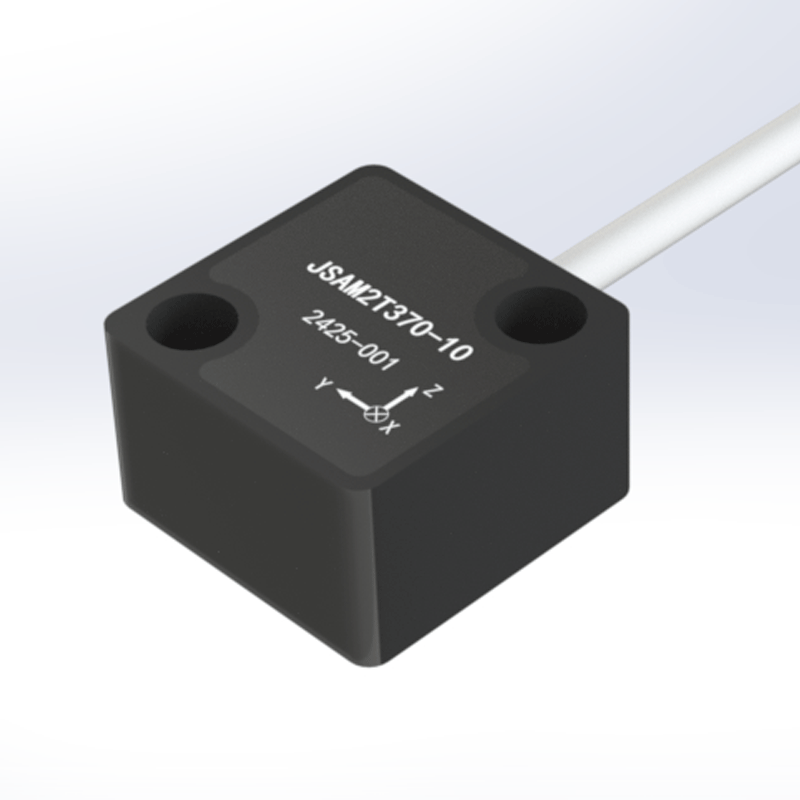
The JSAM2T370 Triaxial Accelerometer is a device that uses MEMS variable capacitance sensing technology and comes with a monolithic aluminum alloy precision-machined housing. It features a selectable measurement range from ±10g to ±5000g and an outstanding shock resistance of up to 20000g; thus, it can be used in different kinds of harsh environments. Its small size and light design (only 10g) make it installation-friendly. Its applications extend to aerospace, heavy machinery, construction equipment, military, and defense sectors.
Product Dimensions
Product Electrical Interface
Wiring color
Red
Black/blue
Green
Yellow
White
Wiring Definition
Power positive
Power ground*
X-axis output
Y-axis output
Z-axis output
* Note: Reference ground for signal measurement
Performance Specifications
The JSAM2T370 sensor is a triaxial acceleration measurement sensor. Its key performance specifications are listed as below.
Unless otherwise specified, all testing was conducted under the following conditions: 12 VDC, 25°C, 50% R.H., and 1 standard atmosphere.
1. Q: This device features an ultrahigh resonant frequency along with a wide bandwidth (up to 10 kHz). What kind of applications is this intended for?
A: The extremely high 10 kHz frequency range is very important when it comes to recording very short-duration fast events. This, in turn, makes the JSAM2T370 most suitable for:
Shock and Impact Testing: Measuring explosive shocks, pyrotechnic events in aerospace, or crash testing.
High-Speed Machinery Monitoring: Detecting the root causes of turbine blades, gear meshing, and other very high-speed rotational equipment where vibrations are at thousands of cycles per second.
Ballistics and Military Applications: Measuring the extremely high G-forces during projectile launch or impact.
2. Q: The datasheet indicates a high "Measurement Range" (e.g., ±5000g) along with an even higher "Shock Survival" rating (20,000g). What is the difference between the two?
A: It is a very important distinction:
Measurement Range (±5000g): This refers to the maximum acceleration that the sensor can accurately measure and produce a linear voltage signal for. If the acceleration goes beyond that during a measurement, the output will clip (saturate).
Shock Survival (20,000g): This is the maximum non-destructive shock the device can physically endure without being damaged. After such a 20,000g event, it can still function accurately within its ±5000g range. This is what provides a huge safety margin for extremely rugged environments.
3. Q: Why does the linearity specification worsen (from <0.2% to <2% FS) with an increase in the measurement range?
A: This is a fundamental trade-off in sensor design. It is highly challenging to maintain high linearity over a very large dynamic range (from ±10g to ±5000g). The MEMS internal element and electronics of the ±5000g model are designed to withstand heavy forces, which may cause slight non-linearities compared to a lower-range, more sensitive model. In most high-G shock scenarios, the most important thing is to be able to capture the full peak without saturation, rather than having perfect linearity.
4. Q: The sensor has an "Insulated Case." What are the benefits of this compared to a conductive case?
A: The use of an insulated (isolated) aluminum case prevents the creation of a ground loop when the sensor is attached to a conductive surface. Ground loops are one of the main reasons for noisy data in measurement systems. Such isolation is especially great when the installation is done on complex structures such as a vehicle chassis, aircraft frames, or electrical machinery, thus offering clean signal integrity by separating the sensor's ground from the host structure's ground.
5. Q: There is such a broad range of models (from ±10g to ±5000g), how can I choose the right one without just guessing or making a mistake?
A: The choice depends on the peak accelerations that you can anticipate:
±10g to ±100g models: These are perfect for high-frequency vibration in heavy machinery, engines, and structural testing.
±200g to ±1000g models: They are appropriate for severe mechanical impacts, for example, in pile driving, punch presses, or automotive crash testing.
±5000g model: It is only for the most extreme cases like explosive shocks, ballistic impacts, and specialized aerospace testing.Key Advice: Choose a range in which your expected peak signals will be between 50% and 80% of the full scale. This ensures a good signal level without the risk of saturation caused by unexpected peaks. The high shock survival rating of the sensor lets you be assured that a miscalculation will not necessarily be the cause of the unit's destruction.
TFC was founded in 2015, with its headquarters located in Changsha, Hunan. It has a standardized workshop of over 6,000 square meters and takes "Making every connection more reliable, making every piece of data more accurate" as its guiding principle, dedicated to providing customers with high-performance component products and solutions. The company has three business divisions: Instrumentation, Connectors, and Sensors. It is a national high-tech enterprise integrating R&D, production, testing, and sales, covering technologies such as signal connection technology, signal conditioning technology, signal switching technology, and signal detection technology.
TFC has obtained National Standard (GB) Quality Management System Certification and Weapon Equipment (GJB) Quality System Certification. It has also established an independent and complete internal quality testing system. All products undergo strict full-process testing in accordance with national standards (GB) and weapon equipment standards (GJB) to ensure compliance and stability of performance.