• Outer shell made from 304 stainless steel
• Ultra-low power consumption: operating current is only 2mA
• Very high impact resistance: 10,000g
• Measurement range can be selected over a wide range: ±50g to ±500g
• MEMS variable capacitance technology
• Weight: 15g
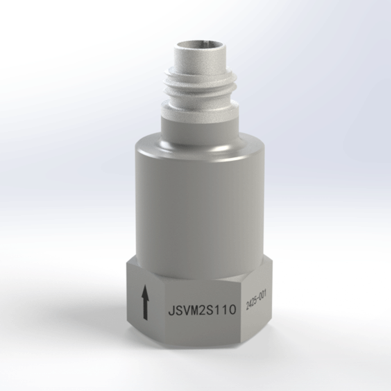
JSVM2S1 Vibration Sensor is based on MEMS variable capacitance sensing technology and is capable of measuring acceleration of the ultra-low frequency range starting from 0 Hz. The device is equipped with a precision-machined 304 stainless steel monolithic housing that provides an exceptional shock resistance of 10,000g; at the same time, the sensor maintains an ultra-low operating current of only 2mA. The combination of the two guarantees both high durability and considerably lower power consumption. The device may be used in crash testing of the automotive industry, the aerospace industry, the rail transportation sector, as well as in other fields that are closely related to these ones.
Product Dimensions
Product Electrical Interface
Wiring color
Red
Black/blue
Green
Yellow
White
Wiring Definition
Power positive
Power ground*
X-axis output
Y-axis output
Z-axis output
* Note: Reference ground for signal measurement
Performance Specifications
The JSVM2S1 is a single-axis vibrometer designed for precise vibration measurement along a single axis. Its key performance specifications are listed as below.
Unless otherwise specified, all testing was conducted under the following conditions: 12 VDC, 25°C, 50% R.H., and 1 standard atmosphere.
1. Q: The device is capable of recording data starting from 0 Hz, and the bandwidth is very wide and can stretch up to 10,000 Hz. What it that practically mean for applications such as automotive crash testing or rail transportation?
A: The 0 Hz (DC) capability in combination with a 10 kHz bandwidth turns the device into an extremely versatile tool when it comes to capturing complex events. During crash testing, it can record the slow tilting of a car before the impact (making use of the DC response), and then it can also very quickly capture the high-frequency, high-G shock of the impact itself. In the case of rail transportation, the device can be used for the low-frequency monitoring of body sway and tilt (0-5 Hz), and at the same time, it can be used for the diagnosis of high-frequency faults from wheels or bearings (hundreds of Hz to several kHz), thus, it can perform all these functions with only one device.
2. Q: The power consumption of the device is said to be extremely low, and is about 2mA, and at the same time, the device has a very high shock survival rating of 10,000g. What is the advantage of this combination, and where is it critically important?
A: The conjunction of these two features is definitely uniquely invaluable for the situations of long-term, unattended monitoring in extreme conditions. Very low power consumption can allow the device to operate for months or even years using battery power in locations that are difficult to wire or remote. In the meantime, the 10,000g shock survival rating can assure that if there is an unexpected extreme event (such as impact or explosion), the device will still be able to survive and operate. The situation is quite critical for safety-critical monitoring on railways, in the case of structural tests of the aerospace industry, or on heavy machinery, where both great power-saving and extreme ruggedness are required at the same time.
3. Q: The "Noise Density" gets worse together with the measurement range (from 35 to 150 μg/√Hz). How does that determine the multiplication factor of the noise level for the specified range needed?
A: That highlights a very important performance trade-off. One should choose the range based on the maximum acceleration that needs to be measured without cutting/clipping.
Select a lower range (e.g., ±50g, 35 μg/√Hz): For the detection of the subtle vibrations and early-stage faults, where high resolution is of great importance. The lower noise floor will allow you to see very small signals quite clearly.
Select a higher range (e.g., ±500g, 150 μg/√Hz): For the capturing of the high-amplitude shocks and impacts (such as a crash or a severe impact). The higher range would prevent signal saturation; however, the trade-off is that the noise floor is much higher, and therefore, very small vibrations will be less distinguishable.
4. Q: The sensor features a "Conductive Case." What are the installation considerations to ensure optimal signal quality?
A: The conductive case means the sensor body is electrically connected to the signal ground (via the "Power Ground" wire). To avoid ground loops—one of the main sources of noisy data—you should provide a single-point ground.
When the sensor is fixed with an M3 screw, the surface for mounting must be clean and conductive so that it can make a good electrical connection with the host structure.
The host structure itself should be grounded properly at one location to your data acquisition system. Don't make multiple, different ground paths because the differences in voltage between them will cause noise (60/50 Hz hum) in your signal.
TFC was founded in 2015, with its headquarters located in Changsha, Hunan. It has a standardized workshop of over 6,000 square meters and takes "Making every connection more reliable, making every piece of data more accurate" as its guiding principle, dedicated to providing customers with high-performance component products and solutions. The company has three business divisions: Instrumentation, Connectors, and Sensors. It is a national high-tech enterprise integrating R&D, production, testing, and sales, covering technologies such as signal connection technology, signal conditioning technology, signal switching technology, and signal detection technology.
TFC has obtained National Standard (GB) Quality Management System Certification and Weapon Equipment (GJB) Quality System Certification. It has also established an independent and complete internal quality testing system. All products undergo strict full-process testing in accordance with national standards (GB) and weapon equipment standards (GJB) to ensure compliance and stability of performance.